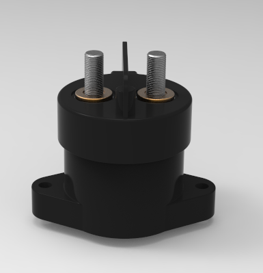
NVR6V-400Y download
1. CCCCE and RoHS compliant;
2. Contacts sealed in ceramic capsules and inert gas;
3. Contacts protected against contamination. e.g oxidation and corrosion;
4. Magnet arc blowout;
5. Coils controlled by PWM (Pulse Width Modulation) to ensure low operation power;
6. Auxiliary contact option;
一、
Product Names and Type Rules
|
|
NVR6V |
- |
400 |
Y |
/ |
750 |
- |
A |
- |
H |
L |
7 |
( ) |
|
Product Type |
NVR6V: Ceramic |
|
|
|
|
|
|
|
|
|
|
|
|
|
Load Current |
400:400A |
|
|
|
|
|
|
|
|
|
|
|
Series Indicator |
Y: Circular Series |
|
|
|
|
|
|
|
|
|
|
Load Voltage |
450:450V
750:750V
1000:1000V |
|
|
|
|
|
|
|
|
Coil Voltage |
A:9~36VDC |
|
|
|
|
|
|
Contact Form |
H:1 Form A of Main Contact
F: 1 Form A of Main Contact + 1 set of Aux. Contact(Default Form A) |
|
|
|
|
Coil Terminal Form |
B: Wire + Connector
L: Wire |
|
|
|
Load Terminal Form |
7: External Thread |
|
|
Special Code |
Customer's special requirements |
二、
Coil Data
@-40℃~85℃
Rated Voltage Vd.c. |
Coil Type |
Operate Voltage
Vd.c. |
Release Voltage
Vd.c. |
Coil Resistance Ω(@23℃) |
Coil Power
(Approx.) W |
|
9~36V |
PWM
Internal
PWM |
≤9 |
≥3 |
4.6×(1±10%) |
40W (start) |
|
4W (keep) |
三、
Contact Data
Main Contact |
Contact Form |
1 Form A |
|
Contact Material |
Copper Alloy |
|
Contact Resistance |
≤1.5mΩ (@400A) |
|
Contact Rating Current |
400A(@350mm2 Copper bar) |
|
Max. Breaking Current |
2000A/320Vd.c.(1 op) |
|
Max. Switching Voltage |
1000Vd.c. |
|
Min. Applicable Load |
6Vd.c./1A |
|
Operate Time |
≤40ms |
|
Bounce Time |
≤5ms |
|
Release Time |
≤25ms |
|
Current Endurance |
400A 持续/ Cont.
450A 300s
600A 120s
1000A 25s |
Aux. Contact |
Contact Resistance |
≤500mΩ(@0.1A) |
|
Max. Carrying Current |
100mA |
|
Min. Applicable Load |
6Vd.c./3mA |
Current Endurance Curve

Notes:
1) The ambient temperature is 85℃, and the cross-sectional area of the copper bar is ≥350mm². Supply rated voltage to coil;
2) The upper limit of the function temperature is 130℃, which is suitable for long-time working; and the upper limit of the safe temperature is 180℃, which is suitable for short-time working; If the temperature exceeds 180℃,the contactor may fail;
四、
Endurance
Electrical Life(Resistivity) |
Making:
|
60Vd.c./400A 1×10³(ops)
|
|
Breaking: |
1000Vd.c./250A 50(ops)
|
|
Mechanical Life |
200,000(ops) |
Notes:
1) Electrical Life tests are conducted in room temperature. Supply rated voltage to coil. On/off ratio is 0.6s:5.4s;
2) Mechanical Life tests are conducted in room temperature. Supply rated voltage to coil. On/off ratio is 0.5s:0.5s.
The above conditions apply to single coil products.
五、
Other Properties
|
Insulation Resistance |
Between Open Contacts |
Before Test:
≥1000MΩ(@1000Vd.c.)
After Test:
≥50MΩ (@1000Vd.c.) |
|
Between Closed Contact and Coil |
Before Test:
≥1000MΩ(@1000Vd.c.)
After Test:
≥50MΩ(@1000Vd.c.) |
Dielectric Strength |
(leakage current≤1mA)
Between Open Contacts
(Leak Current≤1 mA) |
Before Test:
≥3000Va.c.,(50/60 Hz, 1min)
After Test:
≥2250Va.c.,(50/60 Hz, 1min) |
(leakage current≤1mA)
Between Closed Contact and Coil (Leak Current≤1 mA) |
Before Test:
≥2500Va.c.,(50/60 Hz, 1min)
After Test:
≥1875Va.c.,(50/60 Hz, 1min) |
Mechanical Shock-Destructive |
50G |
Mechanical Shock-Functional |
20G |
|
随机振动 Vibration |
10-2000Hz,5G |
六、
Configuration
1. Product Model:NVR6V-400Y/xxx-xx-HL7
Without Aux. Contact
1.1. Outline Dimensions

1.2. 接线图 Wiring Diagram

The built-in PWM load has no polarity,
and the coil has polarity
1.3. Product Weight
|
Specification |
Weight |
|
9~36V |
Approx.435g |
2. Product Model:NVR6V-400Y/xxx-xx-HB7
Without Aux. Contact
2.1. Outline Dimensions

2.2. Wiring Diagram

The built-in PWM load has no polarity,
and the coil has polarity
2.3. Product Weight
|
Specification |
Weight |
|
9~36V |
Approx.432g |
3. Product Model:NVR6V-400Y/xxx-xx-FL7
With Aux. Contact
3.1. Outline Dimensions

3.2. Wiring Diagram

The built-in PWM load has no polarity,
and the coil has polarity
3.3. Product Weight
|
Specification |
Weight |
|
9~36V |
Approx.442g |
4. Product Model:NVR6V-400Y/xxx-xx-FB7
With Aux. Contact
4.1. Outline Dimensions

4.2. Wiring Diagram

The built-in PWM load has no polarity,
and the coil has polarity
4.3. Product Weight
|
Specification |
Weight |
|
9~36V |
Approx.442g |
Notes:
1) All unspecified tolerance please refer to the following table:
|
Dimension(mm) |
<10 |
10~50 |
>50 |
|
Tolerance(mm) |
±0.3 |
±0.5 |
±0.8 |
2) The default shipment of the product includes mounting accessories such as screws, gaskets, and spring pads.
七、
Application Condition
|
Application Condition |
Standards Test Condition |
Operating Condition |
Storage Condition |
|
Temperature |
23 ℃±5 ℃ |
-40℃~+85℃ |
-40℃~+85℃ |
|
Humidity |
25%~75%RH |
5%~85%RH |
5%~85%RH |
|
Altitude |
≤2000m |
≤4000m |
≤4000m |
|
Direction |
Same as Installation Direction |
Vertical |
Forward Packing |
Notes:
1) Since the fixed contact of this product is made of pure copper, if the storage time is longer, the oxidation degree of the contact surface should be checked before use. If oxidation discoloration has occurred, the surface of the contact should be polished to remove the oxide layer before use.The storage environment should avoid condensation and icing.
2) If the storage time exceeds 3 months, the parameters of the contactor should be tested again before use.
3)When the altitude exceeds 2000m, it should be used with reduced capacity according to the requirements of IEC 60947-1.
八、
Others
1. Please avoid foreign bodies, grease or corrosive liquids in the terminal, otherwise it will lead to abnormal heating at contact terminals.
2. Please avoid installation in strong magnetic field (around the transformers, the magnet) and the heating objects nearby.
3. In order to prevent loosening, please use the washer when installing the relay. Please use the M5 screws to install relay, screw locking torque within 3 N·m~4N·m; Damage may occur when it is beyond the range.
4. Please pay attention to the thickness of copper bars and the value of the torque. If it goes beyond the recommended values in the below table , it will cause thread slide or installation is not tight. To avoid short circuit or fire,it’s not suggest fix two copper bus bar at same side.
|
Screw on the load terminal |
Recommended thickness of copper bus bar |
Recommended hole dimension of copper bus bar |
Recommended Flatness of copper bus bar |
Torque |
|
M8 |
4~6mm |
Ф8.1mm~
Ф8.5 mm |
0.1 |
8N·m~10N·m |
5.The rating load of contact is resistive load. Please assure the surge absorption device together with inductive load when using the L/R≥1 ms inductive load (L Load),otherwise it may lead to the decrease of electrical endurance and defective switch.
6. The relay contacts are sealed and filled with gas. When the contact temperature changes, there is internal gas penetrating characteristic.Neputune relays are forbidden to be used at the temperature beyond our suggestion -40 ℃~85 ℃ for long time.
7.In principle, please do not use it when the relay has fallen down.
8.Neptune products are all RoHS2.0 compliant.
9. Neptune reserves the right to change the product. Customers should confirm the version of the specification before purchasing the product.
10. Please contact Neptune Electric (Kunshan) Co., Ltd for more information or support.